LED Stuffed Pumpkin :: Halloween Arduino Project
I usually like to add electronics to my pumpkins. You can follow this step by step guide for making your own your own LED stuffed pumpkin for an Arduino project around Halloween.
What supplies You Need:
- Pumpkin: mine was too small, probably a 8 to 9 pounder would be better.
- LED’s – as many as you want. An Arduino can run 19 independently.
- 220 Ohm Resistor, 1 for each LED you plan on using
- Hook Up Wire: preferably 2 colors, one for ground and one for everything else.
- 9 Volt Battery Supply for your Arduino (or any battery pack that will power you Arduino)
- Solder
- 2 Way Switch (Optional) – if you want an easy way to make two modes of operation.
- Electrical Tape


What Tools You Need:
- Power Drill with a 13/64th size drill bit
- Knife and Spoon to cut open and scrape out the pumpkin guts
- Solder
Step One: Prepare The Pumpkin for its Electronics Stuffing

Cut a hole in the bottom of your pumpkin big enough to comfortably fit your hand into. Pull out all the seeds and scrape out as much of the stringy stuff as you can.
Decide how many and where you want your LEDs to shine through. Mark these points and use a 13/64th inch bit with your power drill to make the holes.
Optional Switch
I had a two way switch sitting around that I thought would add to the aesthetics of my pumpkin. If you are going to make a halloween Arduino project, you might as well make it look electronic. Cut out the shape you think you will need somewhere on the pumpkin body.
You could use a potentiometer for control too – that might be neat.
Step 2: Prepare the LEDs
Cut enough hookup wire to have two pieces for each LED. The length of the hookup wire depends on how big your pumpkin is. I used about 6 inch lengths of hookup wire. This didn’t work out too well for me.
I should have set up one LED, made sure the length would be sufficient, and then gone and cut the others. That is what I recommend you do. If you cut them too long, then stuffing all the stuff in can be tougher, but you can always cut them shorter.
Ideally you will have two separate wire colors – one color for ground and one color for everything else. I used black for ground and blue for just about everything else – it helped a ton when all the wires started looking like spaghetti squash to me.
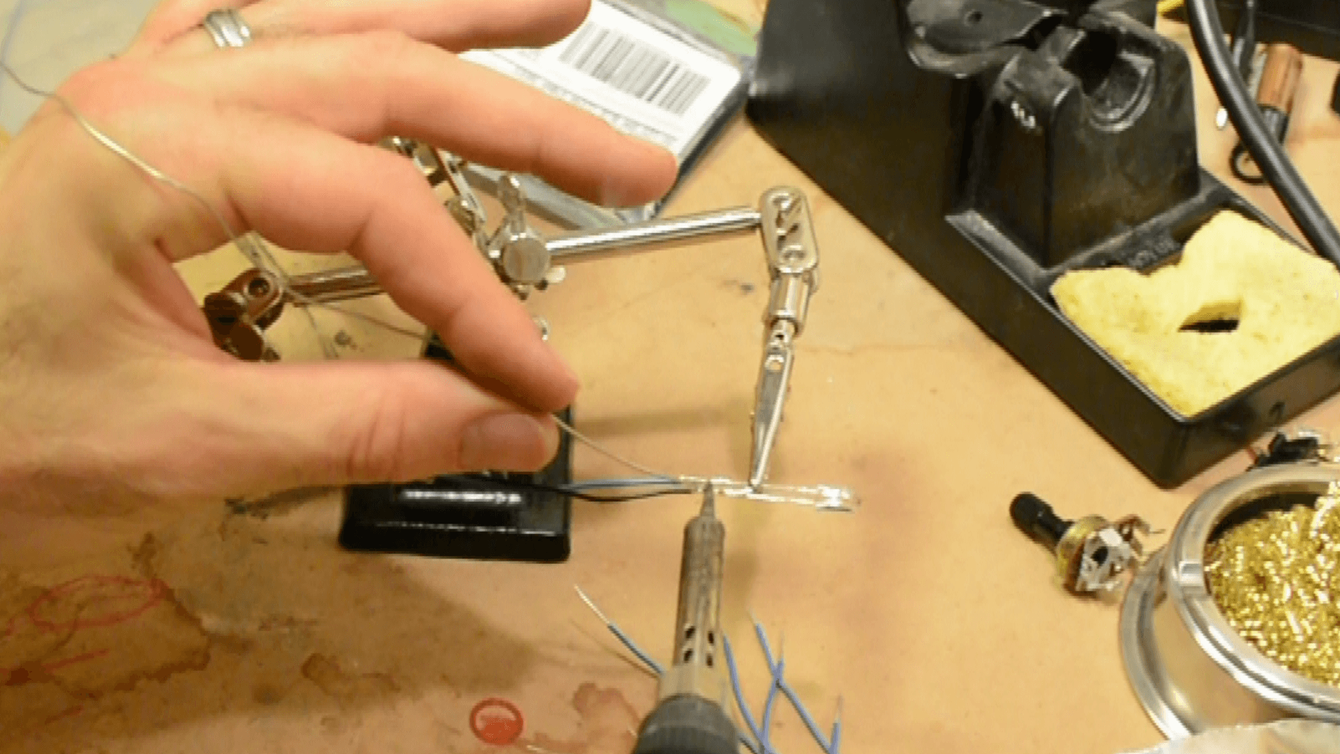
Now strip each wire down far enough to solder, but don’t go too crazy, maybe the width of your pinky finger nail.
Warm up your soldering iron, and solder 220 ohm resistors to the ends of the hook up wire that is connected to the positive sides of the LEDs (I.e. the anode – the longer leg of the LED).
If you decided to use a switch, now would be a good time to solder hookup wire to the switch poles.
The following is optional depending on how much length of hookup wire, and space you have to work with in your LED.
Now this step I wish I would have done – it could have saved me a have hour of frustration.
Place all you resistors into the Arduino pins you plan on using. You will have a bunch of resistors holding up hookup wire with LEDs attached – it will look pretty crazy. When all the resistors are in, take a long piece of electrical tape and sandwich all the resistors together below the resistor body.

Now do it again, above the resistor body, and finally for good measure, do it again around the resistor bodies.
This aligns all your pins when the time comes to plug them into your Arduino, instead of trying to do it one by one. It also isolates the LED from each other, so you don’t inadvertently cross wires.
Step 3: Stuff the Pumpkin with LEDs
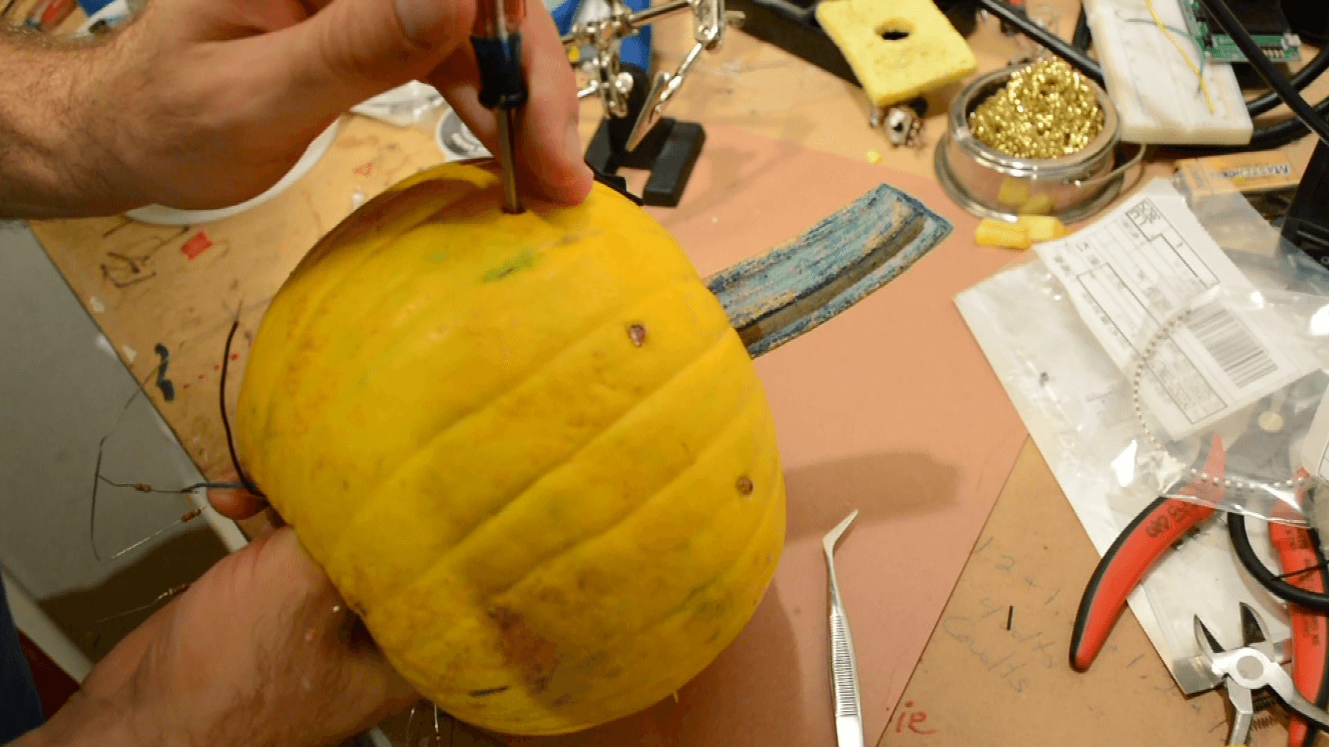
Now place your LEDs into the holes you drilled. The hole size is snug enough to make it a bit difficult but it ensures that the LED won’t draw out if they get tugged a little.
I stuck a screwdriver through the holes to help find them from the inside.
Once all your LEDs are placed, now you need to join all the grounds together. There are a couple ways to do this.
You could solder them all. Depending on how many you have – this could be a messy pain.
You could get a wing wire connecter (the kind used on home electrical wires) and use one of those to join them all together – if I had one conveniently lying around, this is what I would have used.
Whatever method you use, you will then need to connect all these ground wires to the ground on your Arduino. I did this by soldering on an additional piece of hookup wire to the anode of the LEDs and using this to connect all the grounds.
Now connect the resistors to the pins of your Arduino.
Step 3: Load the Code to the Arduino
Now hook your pumpkin…er..uh… your Arduino up to your computer via USB and load the code you want to run your lights.
For a starting point I used the Arrays example, under File > Examples > 05.Control > Arrays. This will get 6 LEDs turning on and off in no specific order.
Below is the code I used.
/* This was originally the Array Example Sketch under File > Examples > 05.Control > Arrays I modified it slightly to make the LEDs track back and forth. created 2006 by David A. Mellis modified 30 Aug 2011 by Tom Igoe modifed 22 Oct 2014 by Michael JamesLED Stuffed Pumpkin :: Halloween Arduino ProjectThis example code is in the public domain. http://www.arduino.cc/en/Tutorial/Array */ int timer = 100; // The higher the number, the slower the timing. int ledPins[] = { 2,3,5,4,6,7,8,9,10,11 }; // an array of pin numbers to which LEDs are attached int pinCount = 10; // the number of pins (i.e. the length of the array) //pins for the switch int switchCenterPin = A0; int switchRightPin = A1; int switchLeftPin = A2; void setup() { //set the mode of the switch pins pinMode(switchCenterPin, OUTPUT); pinMode(switchRightPin, INPUT_PULLUP); pinMode(switchLeftPin, INPUT_PULLUP); // the array elements are numbered from 0 to (pinCount - 1). // use a for loop to initialize each pin as an output: for (int thisPin = 0; thisPin < pinCount; thisPin++) { pinMode(ledPins[thisPin], OUTPUT); }//close for //set the center pin of the switch LOW //this is the signal, that the other swicth positions "read" digitalWrite(switchCenterPin, LOW); }//close setup void loop() { //While the switch is in the Left position, the makes the LEDS race around the pumpkin while(digitalRead(switchLeftPin) == LOW){ // loop from the lowest pin to the highest: for (int thisPin = 0; thisPin < pinCount; thisPin++) { // turn the pin on: digitalWrite(ledPins[thisPin], HIGH); delay(timer); // turn the pin off: digitalWrite(ledPins[thisPin], LOW); }//close for // loop from the Highestpin to the lowest: for (int thisPin = pinCount - 1; thisPin >= 0; thisPin--) { // turn the pin on: digitalWrite(ledPins[thisPin], HIGH); delay(timer); // turn the pin off: digitalWrite(ledPins[thisPin], LOW); }//close for }//close while //While the Switch is in the RIGHT position, turn the LEDs ON one by one, and then off one by one while(digitalRead(switchRightPin) == LOW){ // loop from the lowest pin to the highest: for (int thisPin = 0; thisPin < pinCount; thisPin++) { // turn the pin on: digitalWrite(ledPins[thisPin], HIGH); delay(timer); }//close for // loop from the lowest pin to the highest: for (int thisPin = 0; thisPin < pinCount; thisPin++) { // turn the pin off: digitalWrite(ledPins[thisPin], LOW); delay(timer); }//close for }//close while }//close Loop
Step 4: Hook Up the Battery and Awe Yourself with Blinking LEDs
Once you have loaded your code and done any necessary troubleshooting, you can now unplug your USB cable and plugin your battery pack.
Now it’s time to watch your Halloween Arduino Project glow. Now there might be better ways to improve the world with your electronics skills and time, but regardless, it is fun to watch.


